
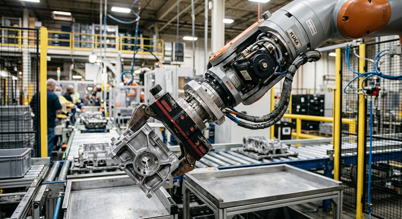
Why Payload Alone Can Lead to the Wrong Robot
A robot can appear to have enough payload for an application and still be the wrong choice. Robot wrist inertia is one reason: the wrist must control not only how much mass it carries but also how that mass is distributed around the wrist while the robot accelerates, decelerates, and changes orientation.
This distinction becomes important when the application uses long grippers, offset tooling, large parts, welding equipment, adapters, valves, sensors, or other equipment mounted away from the wrist. Two loads with the same total mass can impose very different mechanical demands on the robot because they distribute that mass differently
For an industrial buyer, the practical lesson is that the payload figure on a robot specification sheet is only an initial filter. Robot selection also needs to consider center of gravity, inertia, and tooling geometry. Engineers must also evaluate the required orientations and actual production motion.
What Wrist Inertia Means in a Real Robot Application
In practical terms, inertia describes the resistance of a load to a change in rotational motion. Moving significant mass farther from the relevant axis makes the load harder to accelerate, decelerate, or redirect.”
This is why wrist inertia should not be treated as another version of payload. Payload tells the buyer about mass capacity under defined manufacturer conditions. Inertia addresses how the distribution of that mass affects rotational loading.
Imagine two gripper-and-part combinations with the same total mass. One is compact, with most of its mass close to the robot flange. The other uses a long adapter and places the workpiece farther away. They may look equivalent in a simple payload calculation, but they are not mechanically equivalent at the wrist.
The same principle appears when an integrator extends tooling to reach inside a machine, moves an actuator away from a heat source, adds a large welding gun, or handles a long component from one end. Moving mass farther from the wrist can increase inertia even if the total mass has not changed.
Why distance from the wrist matters
Industrial buyers do not need to reduce robot selection to a theoretical physics exercise, but they do need to understand the consequence of mass distribution. Moving a component outward can change the wrist load significantly, which is why apparently small tooling changes can require the load calculation to be checked again.
This is also why evaluating end-of-arm tooling from a total weight figure is incomplete. The integrator needs the geometry and mass distribution of the complete assembly, not simply the weight printed on the gripper datasheet.
Why motion matters as well
The production path affects the evaluation because the robot is not normally holding the load motionless. The wrist may rotate or reorient a part between machines. It may also turn cases during palletizing or change orientation rapidly during handling.
A load that appears manageable during a slow demonstration may therefore require a different assessment when the production cycle demands faster acceleration and frequent orientation changes. The planned motion needs to be evaluated with the complete wrist load rather than assumed from nominal payload capacity.
Payload, Center of Gravity, and Inertia Are Different Checks
A useful buying decision treats payload, center of gravity, and inertia as related but separate constraints. Passing one does not automatically mean that the application passes the others.
Payload is the complete mass carried by the robot.
The payload calculation needs to include everything carried at the wrist. Depending on the application, this can include the workpiece, gripper, fingers, adapters, sensors, valves, fittings, protective components, and other wrist-mounted equipment.
Leaving tooling components out of the calculation creates a false payload margin. This is especially relevant when a robot is selected early in a project, and the end-of-arm tooling becomes heavier as the cell design develops.
The center of gravity describes where that mass acts.
The same payload can produce different loading conditions depending on where its center of gravity is located relative to the robot flange. Compact tooling generally produces a different wrist condition from an assembly that projects a substantial distance away from the flange.
The center of gravity can also change when the workpiece changes. A multi-product gripper may create different load distributions for each product. The gripping position and number of parts can also change the load distribution.
Inertia reflects mass distribution around rotation.
Inertia adds another part of the mechanical picture. It becomes particularly relevant when substantial mass is distributed away from an axis, and the wrist has to rotate or reorient that assembly repeatedly.
The buyer therefore should not ask only, “Is the part below the robot payload?” A better question is, “Does the complete tool-and-part combination satisfy the manufacturer’s permitted payload, centre-of-gravity, and inertia conditions for the motion we intend to run?”
Tooling Decisions Can Change Wrist Inertia After Robot Selection
One of the more expensive ways to discover an inertia problem is after the robot has already been ordered. At the quotation stage, the team may estimate a simple gripper. During detailed engineering, that gripper can acquire longer fingers, an adapter plate, sensors, valves, a tool changer, protective hardware, or additional actuators.
Each change can affect total mass, but its location matters as well. Adding mass close to the flange and adding the same mass at the end of a long tooling structure do not create the same load distribution.
This makes tooling design part of robot selection rather than a secondary task to complete afterward. If the gripper concept is uncertain, buyers should avoid selecting a robot with a narrow mechanical margin based only on an early weight estimate.
The issue is especially relevant in material handling, where gripper geometry and part orientation can dominate the wrist-load calculation. URT’s guidance on what to consider when automating material handling provides additional context on evaluating the complete application rather than the robot arm in isolation.
Long tooling creates a design trade-off
Longer tooling sometimes solves a legitimate cell problem. It can help the robot reach into a machine, clear an obstacle, keep the wrist away from a difficult environment, or approach a part from the required direction.
But extending the tooling can introduce another constraint by moving mass outward. The cell designer therefore has to evaluate the benefit of the extra distance against wrist loading, deflection, clearance, and the motion required to meet cycle time.
Simply selecting a robot with a higher nominal payload does not automatically solve this problem. The proposed robot still has to be checked against its own permitted load conditions.
Why Cycle Time Can Expose an Inertia Problem
A cell can complete its programmed path during commissioning and still have a poor production design. Demonstrating that the robot can physically move a load is different from confirming that the complete configuration is appropriate for the intended production duty.
Production may require frequent starts, stops, wrist rotations, and changes of orientation. If cycle-time pressure leads the project team to demand more aggressive motion after the tooling has been finalized, the load condition needs to remain within the manufacturer’s requirements.
This is an important distinction for buyers comparing robot proposals. Buyers should not judge a proposal only by whether the arm reaches every point and carries the nominal workpiece. The engineering assessment should also consider the real tool, actual part, required orientations, and expected production movement.
Cycle time also belongs to the wider cell rather than the robot alone. Part presentation, machine signals, gripping time, and upstream or downstream equipment can determine output even when the robot has unused motion capacity. This is one reason robot selection should avoid treating maximum motion capability as the only route to higher production.
Where Industrial Buyers Commonly Get the Evaluation Wrong
Most wrist-load mistakes begin with an incomplete description of the application rather than a failure to understand the robot catalogue. The purchasing team may know the workpiece weight while the final tooling geometry, orientation, and motion remain undefined.
Another common problem is comparing robots using payload labels alone. A higher payload rating can be relevant, but it does not eliminate the need to verify the manufacturer’s load conditions for the exact robot variant and final configuration.
There is also a risk in assuming that the gripper supplier’s quoted mass is the complete tooling load. Fingers, adapters, brackets, hoses, fittings, valves, sensors, and product-specific additions can change the final assembly.
Finally, a production change can invalidate an earlier calculation. A new part may weigh approximately the same as the original product. However, its dimensions or gripping point may differ. That change can alter the center of gravity and inertia even when the total payload changes very little.
The same decision principle applies more broadly to robot capability. For example, accuracy and repeatability must be evaluated in their real production context rather than treated as isolated catalogue values. Wrist loading requires the same application-based approach.
When the Robot Should Be Reconsidered
An inertia calculation is not intended to prove that a preferred robot can be made to work. It is a selection constraint. If the complete tooling and workpiece configuration falls outside the manufacturer’s permitted load conditions, the application or robot choice needs to be reconsidered.
One option may be to redesign the tooling so that mass is positioned closer to the wrist. Another may be to change the gripping point and reduce unnecessary tooling mass,
The engineering team can also revise how the part moves during transfer. Whether these changes are practical depends on the process.
In other cases, the correct decision may be a different robot. This can occur even when the original robot has sufficient nominal payload. Its permitted load distribution may not suit the required tooling and motion.
There are also applications where solving the wrist-load problem creates unacceptable compromises elsewhere. Shortening tooling may remove required machine clearance, changing the grip point may make part retention less stable, or reducing motion may prevent the cell from meeting the required cycle. In those cases, the complete cell concept should be reviewed rather than optimizing one parameter in isolation.
Specification Verification Before Cell Design
There is no useful universal wrist-inertia limit for industrial robots. Permitted loads depend on the manufacturer, robot model, exact variant, and the conditions defined in the relevant technical documentation.
For that reason, numerical wrist limits should not be transferred from a similar robot, another variant in the same family, or a third-party specification database. The exact robot model needs to be checked against official manufacturer documentation and the manufacturer’s load diagrams or approved calculation tools.
The final calculation should represent the production configuration, including the workpiece and all equipment mounted on the wrist. It should also reflect the required load orientation and movement rather than a simplified configuration chosen only because it passes the calculation.
The same engineering requirement applies when a buyer purchases a used or refurbished robot. A lower purchase price does not make an unsuitable load condition acceptable. Buyers considering second-hand equipment should also evaluate the wider questions covered in URT’s guide to buying refurbished industrial robots, including condition, controller, and integration requirements.
What to Check Before Approving the Robot and Tooling
Use this checklist after the tooling concept and production motion are sufficiently defined. The purpose is to prevent a preliminary payload estimate from becoming the final robot-selection decision without the necessary wrist-load verification.
- Calculate the mass of the complete wrist-mounted assembly, including the workpiece and all tooling components.
- Define the center of gravity using the real tooling and gripping configuration.
- Evaluate the inertia of the complete load rather than relying on payload alone.
- Check whether different products, grip positions, or tool configurations create different load cases.
- Include adapters, fingers, sensors, valves, fittings, protective equipment, and other additions that may appear during detailed design.
- Review the actual wrist orientations and production movements that the cycle requires.
- Confirm that cycle-time changes do not invalidate assumptions used during initial selection.
- Use official manufacturer load diagrams or approved calculation tools for the exact robot variant.
- Repeat the assessment when tooling, workpiece geometry, gripping position, or production duty changes.
The objective is not simply to obtain a robot that can lift the part. It is to select a robot, tooling arrangement, and production motion that remain inside the manufacturer’s permitted load conditions while the cell performs the job it was actually designed to do.
FAQ
Is robot wrist inertia the same as payload?
No. Payload relates to the mass carried by the robot under the manufacturer’s defined conditions. Wrist inertia relates to how that mass is distributed around rotational axes. A load can satisfy a nominal payload requirement and still require further evaluation because of its centre of gravity or inertia.
Can a robot be under its payload limit but still be unsuitable?
Yes. Payload is only one part of the load assessment. The complete tooling and workpiece must also satisfy the applicable centre-of-gravity, inertia, and other load conditions specified by the manufacturer for the exact robot.
Does a longer gripper increase wrist inertia?
It can. A longer gripper can move significant mass farther from the wrist, changing the load distribution and increasing inertia. The result depends on the mass and geometry of the complete tooling and workpiece configuration.
Should gripper accessories be included in the wrist-load calculation?
Yes. The assessment should represent the complete load carried by the robot, including the workpiece, gripper, fingers, adapters, sensors, valves, fittings and other wrist-mounted equipment relevant to the final configuration.
Does changing the workpiece require the inertia calculation to be checked again?
It may. A new workpiece can change mass, center of gravity, gripping position, or load distribution. Even a part with similar weight can create a different wrist condition if its geometry or required orientation changes.
Can reducing robot speed solve an excessive wrist-inertia condition?
Do not assume that it does. Motion requirements can affect the mechanical demands of an application, but permitted load conditions must be evaluated according to the exact manufacturer’s documentation and approved engineering methods. A configuration outside the specified limits should not be accepted simply because the planned program is slower.
Who should verify wrist inertia before a robot is purchased?
The robot and tooling selection should be verified by the engineering or integration team responsible for the complete application, using accurate load data and the manufacturer’s documentation or approved calculation tools for the exact robot variant.
Talk to URT About Robot Wrist Inertia
If you are evaluating robot wrist inertia, contact URT. We will give you a direct, technical answer based on your actual production requirements.