
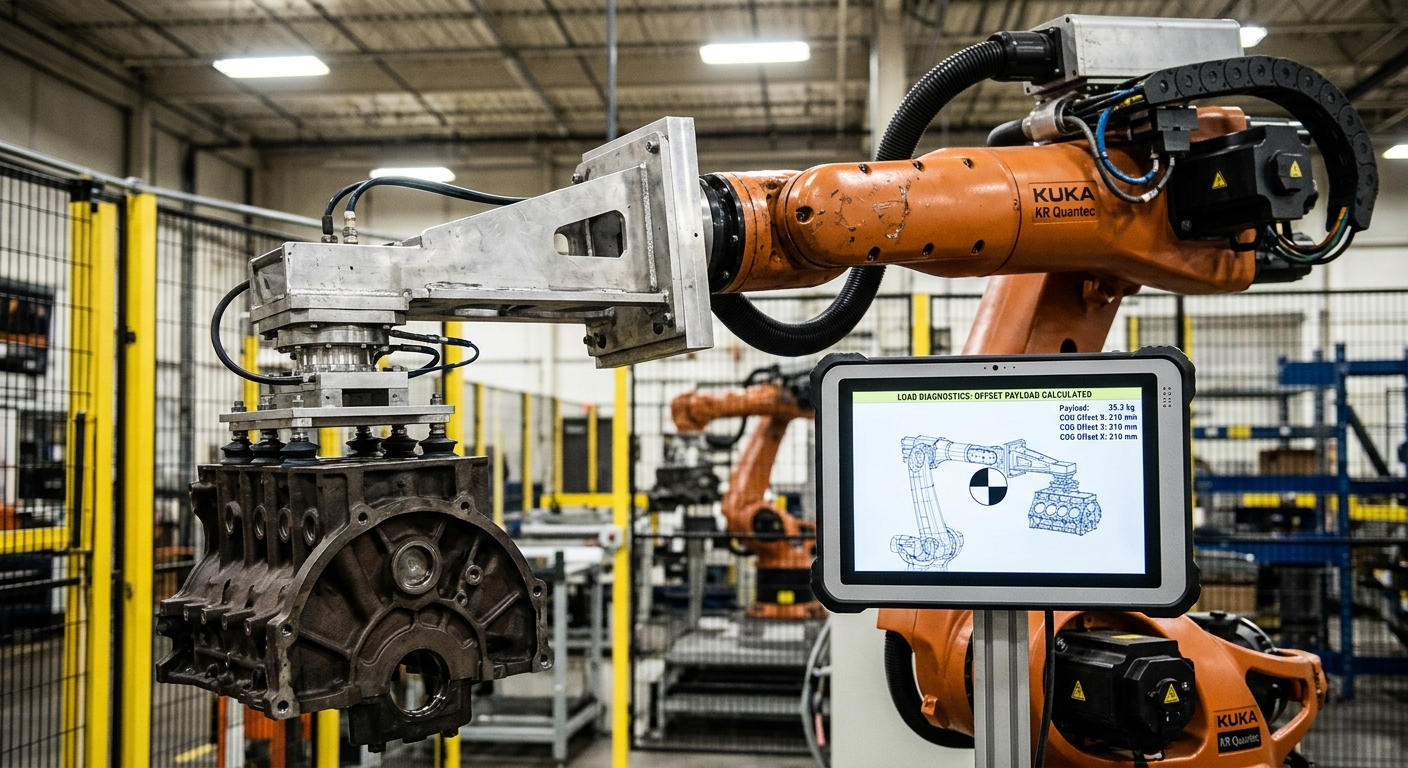
Why Payload Capacity Can Give the Wrong Answer
A robot can appear to have enough payload for an application and still be mechanically unsuitable. The missing variable is often the robot center of gravity: where the combined mass of the tool and workpiece acts relative to the robot wrist. Moving that mass farther from the wrist changes the mechanical demand even when the total mass has not changed.
This matters because the robot does not carry only the production part. The wrist may also support a gripper, fingers, adapters, sensors, valves, fittings, protective equipment, cables and other components. Their positions affect the complete load configuration, not just the number that appears on a scale.
For that reason, nominal payload should be treated as an initial filter rather than final approval. Robot selection needs to consider payload, center of gravity, inertia, required orientations and the motion profile together. The tooling that makes an application possible can also be what pushes the robot outside its permitted load conditions.
Center of Gravity Changes the Load Seen by the Robot Wrist
Two tooling assemblies can have the same total mass and create very different conditions at the wrist. A compact gripper with most of its mass close to the mounting flange is mechanically different from a long tool that places the same mass farther away.
The practical reason is leverage. As the load moves farther from the wrist, the moment acting on the wrist increases. The robot therefore has to control not only how much mass is attached, but where that mass is positioned relative to its mechanical axes.
This distinction becomes particularly important with long grippers, welding equipment, large vacuum frames, multi-product tooling, machining packages and handling tools designed to reach inside machines. A tooling modification that adds relatively little mass can still materially change the load condition if that mass is added far from the wrist.
The Workpiece Changes the Calculation
The tooling should not be evaluated empty if the robot will carry a part during production. The relevant load is the complete moving assembly under the operating condition being evaluated. That means the workpiece and everything mounted to the wrist need to be considered together.
The center of gravity can also change between production conditions. A gripper handling several product formats may carry different masses or geometries. A long workpiece may place its mass differently from a compact part even when their weights are similar.
This is one reason a robot selected around a single nominal payload value may become problematic after tooling design is finalized. The load configuration used during robot selection should represent the real production assembly rather than an early estimate of the part alone.
Center of Gravity and Inertia Are Related but Not Interchangeable
Center of gravity describes where the combined mass of the wrist-mounted assembly is concentrated. Inertia describes how that mass resists changes in rotational motion. Both influence whether the robot can execute the required movement within its permitted loading conditions.
A long tool is a useful example. Extending the tool may solve an access problem by allowing the gripper to reach into a machine, around a fixture or past an obstruction. However, moving mass farther from the wrist can increase both the mechanical moment and rotational inertia.
The effect becomes more important when the application requires rapid changes in orientation. Fast wrist rotations and aggressive acceleration or deceleration can make an offset load more demanding than its static mass suggests. A robot that can physically hold the assembly is not necessarily approved to move it through the required cycle.
This is why payload capacity alone cannot confirm tooling suitability. The manufacturer’s load diagrams or approved calculation tools should be used to evaluate the complete configuration against the exact robot model and intended motion.
Tooling Design Can Consume Mechanical Margin Quickly
End-of-arm tooling often evolves after the first robot concept has been selected. A simple gripper gains longer fingers. A bracket is added to improve access. Sensors are repositioned. A protective plate, valve manifold or secondary gripping mechanism becomes necessary. Individually, these changes may appear minor.
Together, they can alter both mass and mass distribution enough to change the suitability of the robot. This is why tooling design and robot selection should not be treated as independent engineering tasks.
Long Tooling Solves Access but Creates Another Constraint
Moving the tool farther from the flange may improve reach into a fixture or machine without requiring a different robot position. The trade-off is increased mechanical leverage, potentially higher inertia, more deflection and additional clearance requirements.
The better solution is not automatically a larger robot. Cell layout, robot mounting, fixture position and tooling geometry should also be reviewed. Sometimes changing where the robot stands or how the part is presented allows a more compact tool and reduces wrist loading at the same time.
This interaction is especially relevant in applications where the robot must enter confined equipment. URT’s guide to robotizing CNC machine loading and unloading without creating bottlenecks shows why the complete machine interface and production flow need to be considered rather than selecting the robot in isolation.
Tool Changers and Multi-Function EOAT Must Be Included
Automatic tool changers, adapters, couplings, manifolds and secondary mechanisms become part of the wrist load when they travel with the robot. The same applies to equipment added later to support additional products or processes.
A flexible tool can reduce changeovers, but flexibility is useful only if the final assembly remains within the robot’s permitted mechanical conditions. Adding functionality without recalculating the load can remove the margin that existed when the original cell was commissioned.
Motion and Robot Posture Affect the Real Application
A load calculation should represent the movement the robot will actually perform. The required orientations, acceleration, rotation and production cycle all matter because an industrial robot is a dynamic system rather than a static lifting device.
Consider a handling application in which the robot picks a component horizontally and rotates it before placing it vertically. The wrist experiences a changing mechanical condition as the assembly changes orientation. Tooling that appears acceptable at the pickup point still needs to be evaluated through the complete path.
Robot posture also matters to overall cell performance. A path near joint limits, difficult wrist orientations or restricted clearance can create a different integration problem even when the load itself is acceptable. Reach should therefore be evaluated through the required tool center point positions and orientations, not simply against the robot’s maximum reach envelope.
Material handling projects demonstrate this interaction clearly. URT’s discussion of factors affecting robot material handling applications provides additional context for evaluating the robot as part of the complete handling process.
Why Tooling Changes Should Trigger a New Load Review
A cell that was correctly engineered at commissioning can move outside its original design assumptions later. Production teams may introduce a heavier product, longer fingers, a different gripper, additional sensors or protective hardware without changing the robot itself.
The fact that the robot previously ran successfully does not prove that the modified configuration remains acceptable. The new assembly changes the conditions that were originally evaluated.
This creates a maintenance and reliability issue as well as an engineering issue. Operating outside manufacturer-approved loading conditions can increase mechanical demand on the wrist and drivetrain. It may also require reduced motion or a different tooling arrangement before production can continue within approved limits.
Plants reviewing reliability problems should therefore include tooling configuration in the investigation rather than assuming that every motion-related issue originates inside the robot. Broader approaches to minimising downtime in robotic automation should consider changes to the complete production system, including the load attached to the robot.
Specification Verification Before Cell Design
There is no universal center-of-gravity limit that can be applied to every industrial robot. Permitted payload, load position, wrist moment and inertia conditions depend on the manufacturer, exact robot model and variant. They must be verified using official documentation for the robot being evaluated.
Model variants matter. A suffix or configuration change can correspond to a different mechanical arrangement or permitted load condition. Data from a related robot family, a similar model or a third-party specification page should not be substituted for the exact model.
Before tooling is released for manufacture, the engineering team should verify the robot model plate and the manufacturer’s current load documentation or approved load-calculation method. Final tooling mass, workpiece mass, center-of-gravity position and inertia should be checked using the real configuration.
This verification should happen again if the tool, workpiece, adapter, protective equipment or production motion changes substantially. A load calculation is not merely a robot purchasing check; it is part of maintaining a valid cell configuration over its operating life.
When a Robot With Enough Payload Is Still the Wrong Choice
A robot should not be selected simply because its nominal payload exceeds the combined mass of the part and gripper. If the application requires long offset tooling, large workpieces, rapid wrist rotations or orientations that create unfavorable load conditions, another configuration may provide more appropriate mechanical margin.
The answer is not necessarily to move immediately to the next payload class. A heavier robot may increase cell footprint, purchase cost and integration requirements without addressing the underlying reason the tooling became long or poorly balanced.
The engineering team should first determine why the load is offset. Repositioning the robot, changing the fixture, shortening the tool, redistributing components or presenting the workpiece differently may improve the configuration without increasing nominal robot capacity.
Robot selection should therefore follow the application rather than precede it. The same principle applies when deciding which process to robotize first: controlled production requirements should define the automation architecture, rather than adapting the process around equipment selected too early.
What to Check Before Approving the Robot and Tooling
Use this checklist after the gripper concept and production part range are sufficiently defined. It is most useful before final robot selection and should be repeated whenever the wrist-mounted configuration changes.
- Calculate the complete moving mass. Include the workpiece, gripper body, fingers, adapters, tool changers, sensors, valves, fittings, protective equipment and other wrist-mounted components.
- Determine the complete center of gravity. Do not assume the gripper manufacturer’s stated value represents the final assembly once adapters, components and the production part are added.
- Evaluate every relevant product format. Different parts can change both total mass and load distribution.
- Check inertia as well as payload. Long tooling and offset workpieces can create demanding rotational conditions even when their total mass is below nominal payload.
- Use the exact robot model documentation. Verify the configuration against manufacturer load diagrams or approved calculation tools rather than data from a related model.
- Review the production motion. Include required orientations, wrist rotations, acceleration, deceleration and cycle requirements.
- Check the complete path. Confirm tool orientation, joint limits, clearance, fixtures, machine openings and recovery movements.
- Repeat the calculation after tooling changes. Longer fingers, added sensors or new product formats can invalidate the assumptions used during initial engineering.
The purpose of these checks is not simply to prove that the robot can carry the tool. It is to confirm that the complete mechanical configuration remains suitable for the production motion expected from the cell.
FAQ
Can a robot be under its payload limit and still be overloaded?
Yes. Nominal payload is only one loading condition. An offset center of gravity or excessive inertia can make a tooling configuration unsuitable even when the total mass is below the robot’s stated payload capacity. The complete load must be checked against the manufacturer’s requirements for the exact robot.
Does the gripper count as part of robot payload?
Yes. The complete wrist-mounted assembly must be considered, including the gripper, fingers, adapters, sensors, valves, fittings, protective equipment and the workpiece being carried. Evaluating only the part mass understates the real load.
Why does a longer gripper affect robot performance?
A longer gripper can move mass farther from the wrist. This increases mechanical leverage and can increase inertia, while also introducing additional deflection and clearance requirements. The final effect depends on the complete tooling configuration and robot motion.
Does center of gravity stay the same for every product?
Not necessarily. Different workpiece masses, dimensions and gripping positions can shift the combined center of gravity of the tool and part. Multi-product cells should therefore evaluate the relevant load cases rather than assuming one product represents every configuration.
Should center of gravity be recalculated after changing robot tooling?
Yes, when the modification changes the mass or mass distribution of the wrist-mounted assembly. Longer fingers, new adapters, tool changers, sensors, protective equipment or different workpieces can change the load condition enough to require a new verification.
Can slowing the robot solve a center-of-gravity problem?
Reduced acceleration or motion may change dynamic loading, but it should not be assumed to make an otherwise unacceptable configuration valid. The permitted operating conditions must be determined from the manufacturer’s documentation or approved calculation method for the exact robot and load.
Should the robot or the tooling be selected first?
The application requirements should be defined before either is finalized. Robot and tooling selection are interdependent because tool geometry affects reach, center of gravity and inertia, while robot capacity and cell layout constrain what tooling can be used. Final approval should evaluate them as one mechanical system.
Talk to URT About Robot Center of Gravity and Tooling
If you are evaluating robot center of gravity and tooling limits, contact URT. We will give you a direct, technical answer based on your actual production requirements.